The Horton fan clutch has one of the most important functions in truck’s operation, yet it is one of the most overlooked components and least maintained item. In this “What to Look for” feature, we’ll explain how the Horton fan clutch works, what weekly maintenance it requires and importantly what to keep an eye on.
A Horton fan clutch’s prime function is to engage and disengage the engine fan with a clutch controlled by an air actuated solenoid valve. On modern vehicles the solenoid receives signals to turn on and off from the engine’s ECU. On older trucks the signals are sent from the temperature sensor. The clutch engages and makes the fan turn when the valve opens, sending air pressure to overcome a spring and push the Piston Friction Disc (PFD) against the friction material. It disengages when the valve closes, allowing the clutch solenoid to exhaust air and let the spring return.
Most vehicles also have a manual override switch which will allow the driver to activate the fan on the approach to hill bring the engine temperature down. Conversely on a long descent a professional driver will manually activate the fan to help aid engine retardation, because the fan soaks up 30 to 40 horsepower.
One of the most common causes of premature failure in a Horton fan clutch is clutch slippage caused by excessive heat, but its not all bad news. Since mid 1996 all HTS type fan clutches with a 9.5-inch (241mm) diameter are now equipped with the System Sentry help prevent clutch failure. System Sentry is designed to act as a thermal fuse, causing the fan clutch to disengage if it encounters excessive heat build up.
How this works
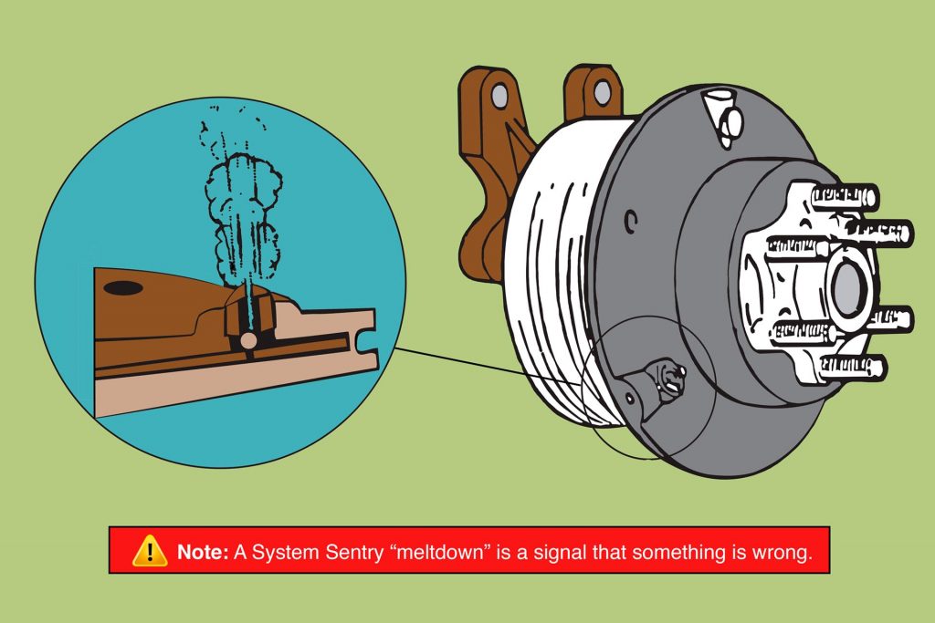
In the event of fan clutch slippage, heat builds up at the outer edge of the Piston Friction Disc (PFD). This heat works its way toward the centre of the fan clutch. When damaging levels of heat reach the System Sentry the fuse will melt. This allows air pressure in the fan clutch to drop, disengaging the fan clutch immediately.
When the System Sentry has released the fan clutch, it has done this to protect your investment. This protective action also alerts you that there is a problem, so you can troubleshoot and repair the problem immediately. Catching problems in the early stages will keep damage and downtime to a minimum
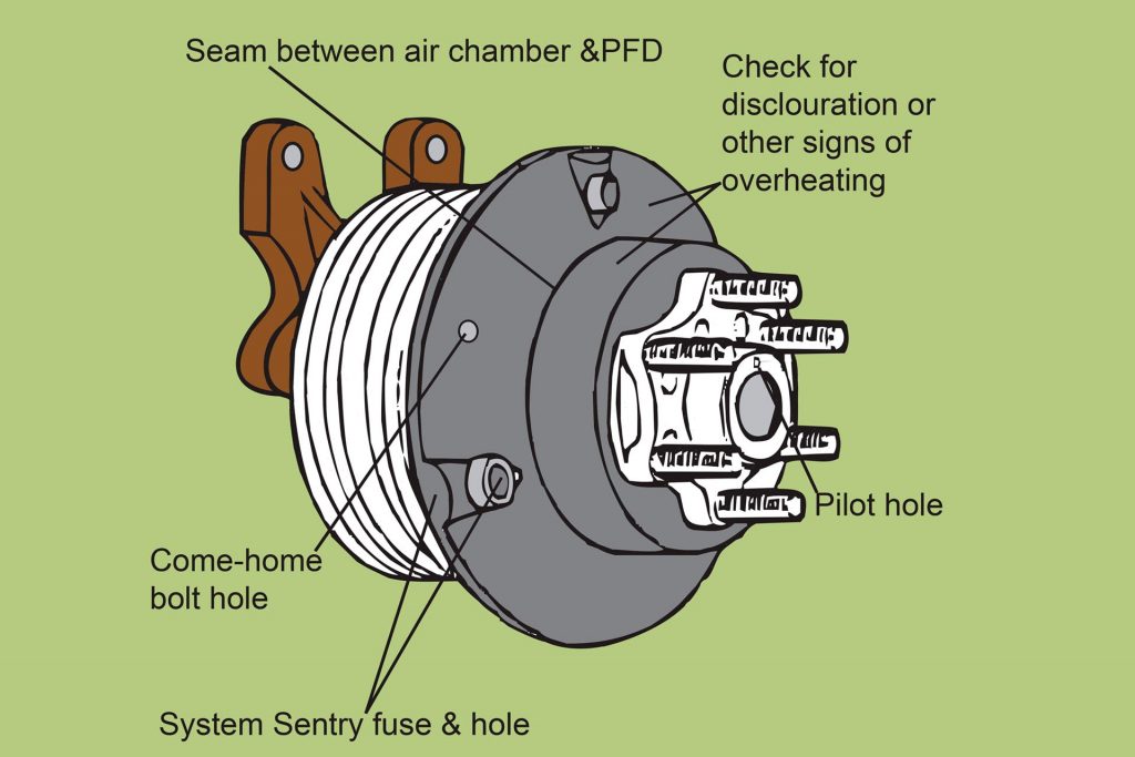
The System Sentry Fuse part number F994098 is located in one of the raised nodes on the front section of the Disc Piston Assembly.
Trouble Shooting
A System Sentry “meltdown” is a signal that something is wrong and action is required to determine what went wrong.
Fan Blades
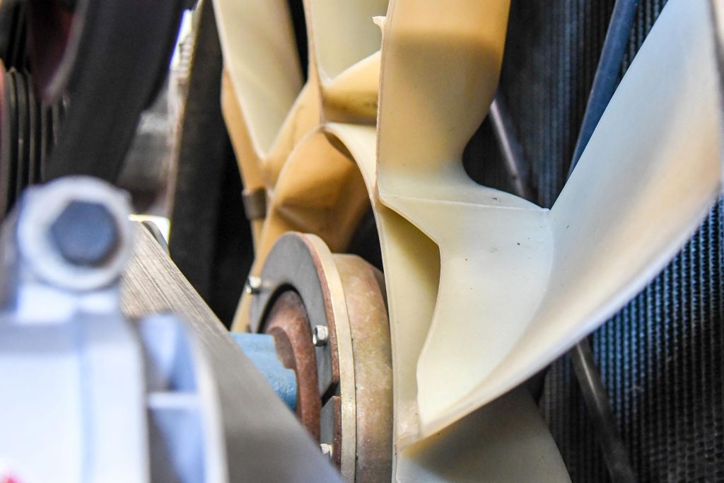
Fan blades should be checked for correct clearance to radiator, shroud and engine components. Check, locate and remove anything that may be an obstruction to the fan blade. Check that there are no cracks or splits in the fan blades that might cause the fan to run out of balance.
Clutch Slippage
A fan clutch needs 100 psi (6,8 bar) for solid engagement. Look for a problem that is causing partial engagement – usually air leaking past the solenoid valve seals into the airline causing a pressure build-up. Is there a pressure drop causing partial disengagement? This usually is caused by an inoperative solenoid, Airline blockage, up-stream air leaks, air leaks from the fan clutch body itself or low air pressure.
Maintenance
Routine inspection of the Horton Fan Clutch should be carried out at 200,000km intervals. Remove and plug airlines at the Fan Clutch input. Loosen fan belts, rotate the pulley and feel for smooth rotation of bearings. Repeat this procedure on the front section of the Fan Clutch. Check friction facing for wear, the friction facing should be approximately 4mm thick.
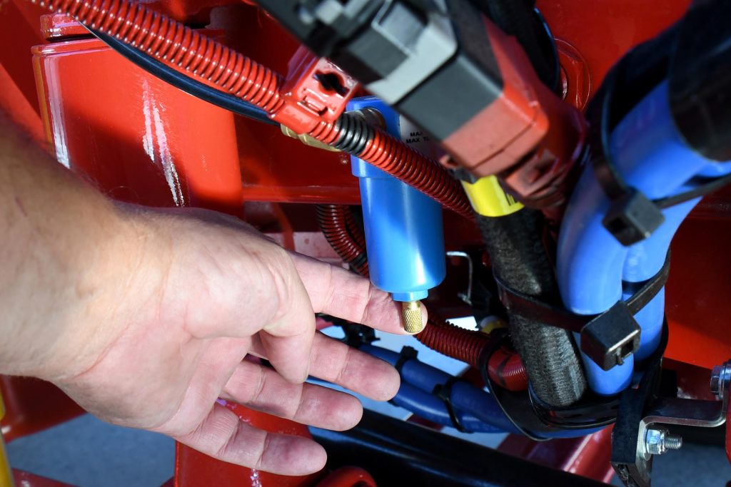
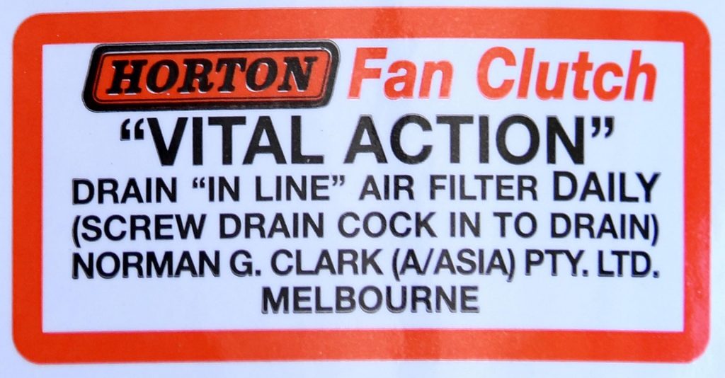
Drain the inline air-filter daily to release any moisture.
Manual Lock up procedure
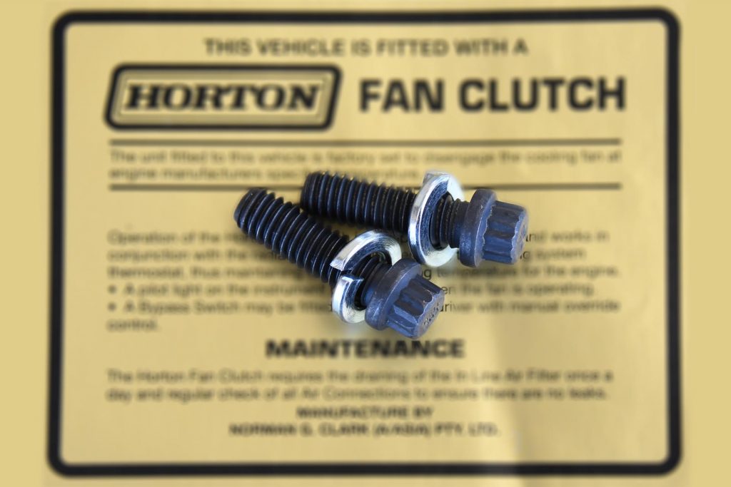
If for some reason your Horton fan will not engage, such as when the System Sentry fuse has released you can manually engage the fan with the two bolts in the emergency bolt kit.
First disconnect and plug the airline to Fan Clutch. Align the two bolt-holes in the front section of the Fan Clutch with the two tapped holes located in the pulley sheave. Install the two Grade-8 5/16 Whitworth socket head cap screws. Tighten screws very firm, clamping of the clutch not the screws provides the turning force. If you need to purchase a replacement set of lock up bolts their part number is F21610.